Fire & life safety and circulation
How everyone gets out safely, and how guests, staff and vehicles move without crossing.
Fire & life safety
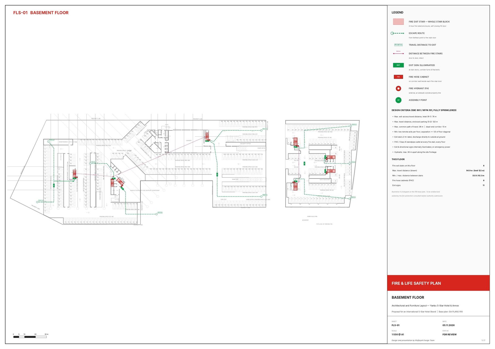
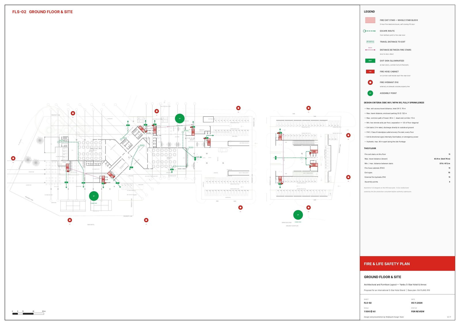
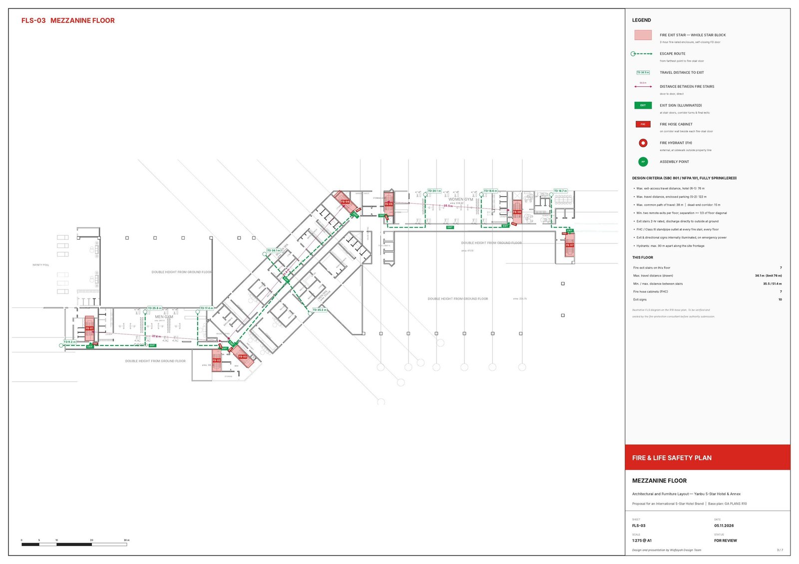
SBC 801 and NFPA 101, fully sprinklered. Escape routes lead to protected fire stairs, final exits at ground level and the assembly points.
| Sheet | Floor | Fire stairs | Max. travel (drawn) | Limit | Status |
|---|---|---|---|---|---|
| FLS-01 | Basement | 8 | 94.9 m | 122 m (car park) | ✓ OK |
| FLS-02 | Ground floor & site | 11 | 63.9 m | 76 m | ✓ OK |
| FLS-03 | Mezzanine | 7 | 36.1 m | 76 m | ✓ OK |
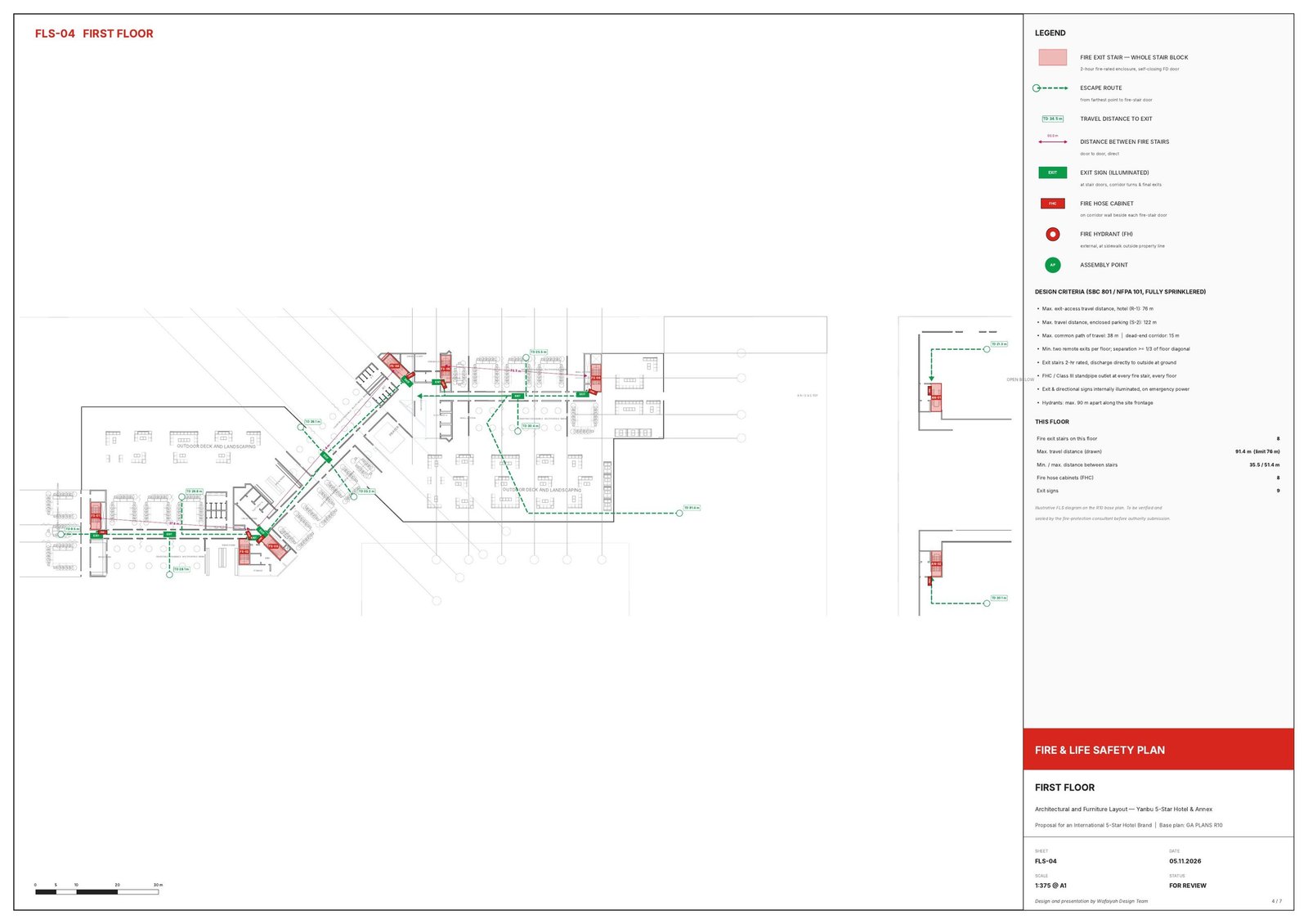
| FLS-04 | First floor | 8 | 91.4 m | 76 m | Review – longer than the limit; resolved in the R17 FLS set |
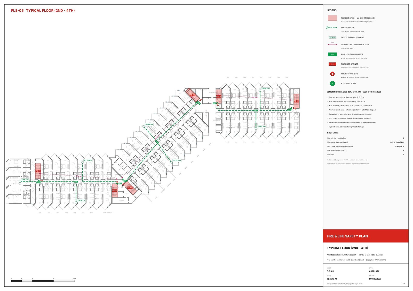
| FLS-05 | Typical floor 2nd–4th | 6 | 36.1 m | 76 m | ✓ OK |
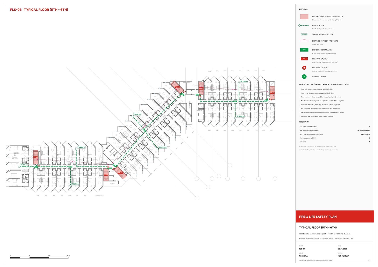
| FLS-06 | Typical floor 5th–6th | 6 | 36.1 m | 76 m | ✓ OK |
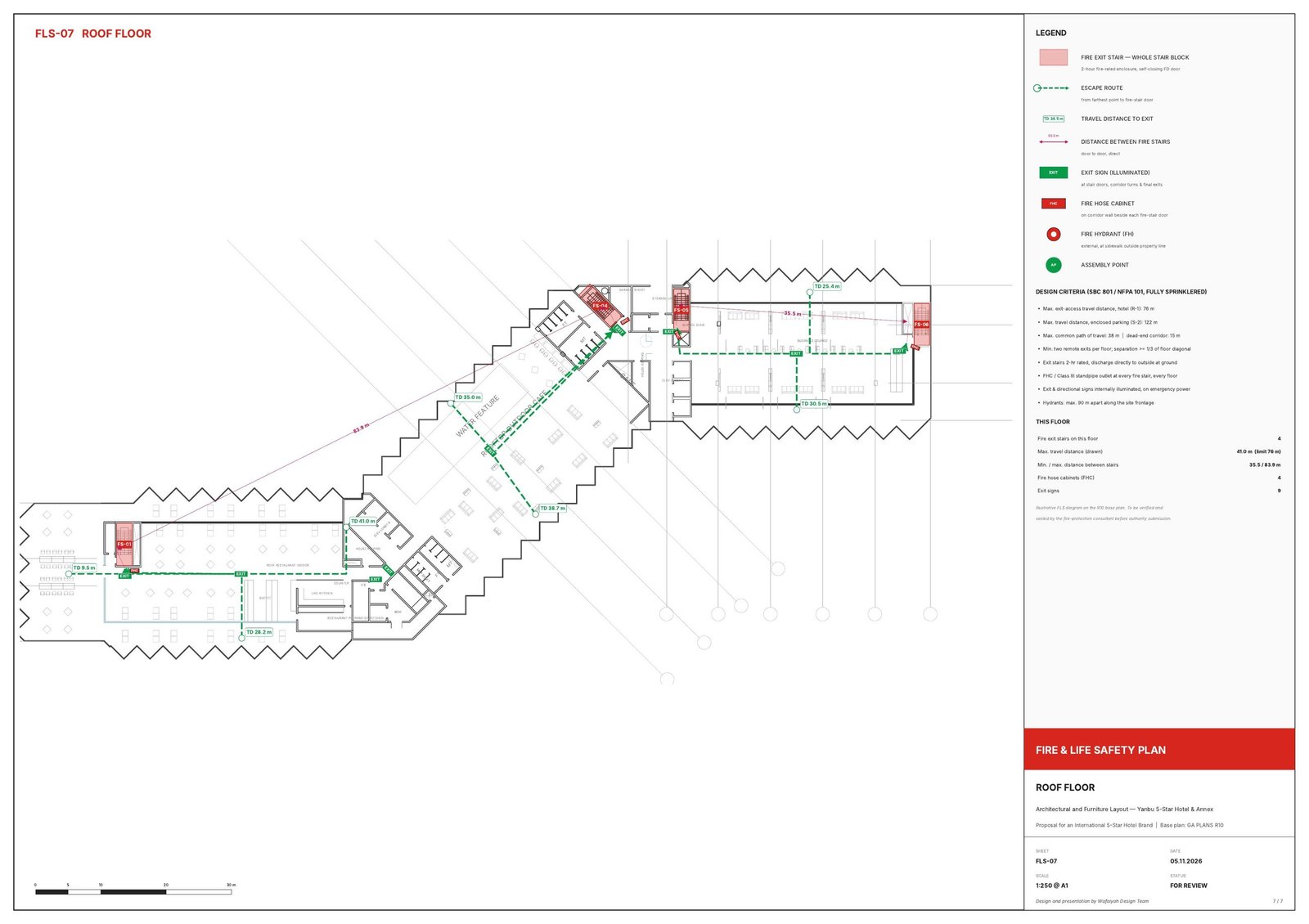
| FLS-07 | Roof floor | 4 | 41.0 m | 76 m | ✓ OK |
Illustrative FLS on the R10 base plans; to be verified and sealed by the fire-protection consultant before Civil Defence submission. Criteria: common path 38 m, dead end 15 m, two remote exits per floor, 2-hour stairs discharging outside, FHC at every stair door.
Circulation & function
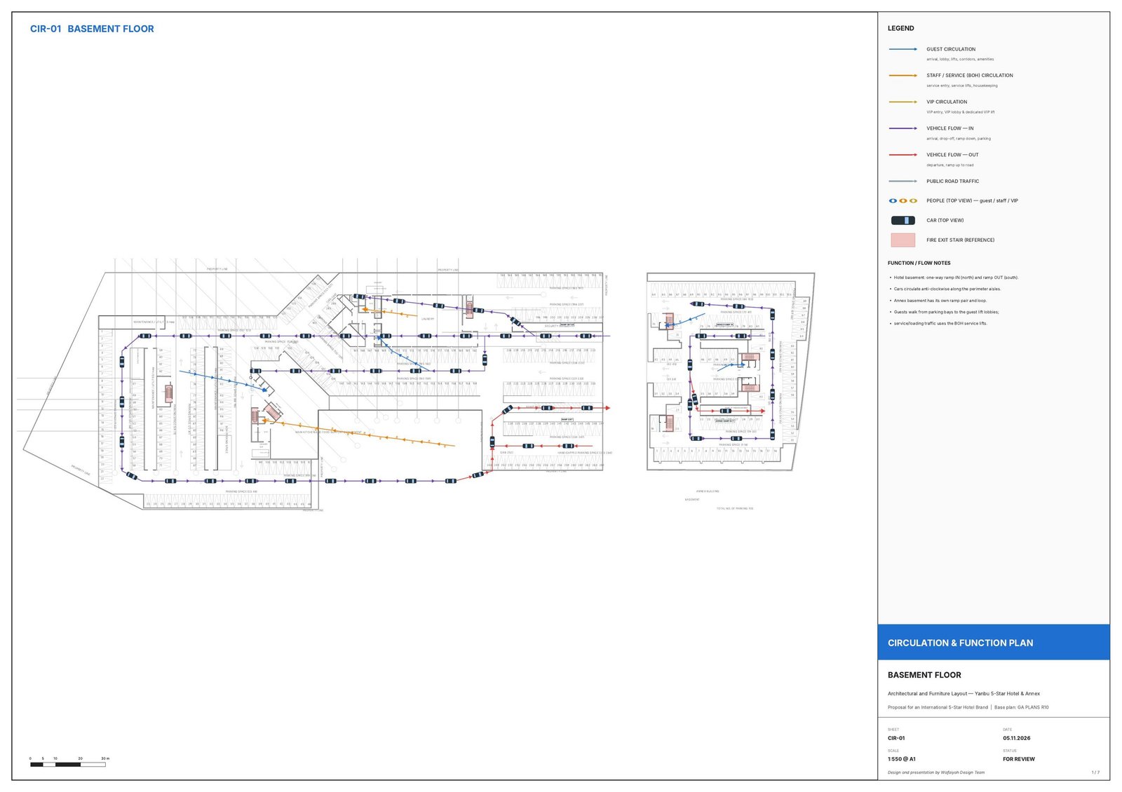
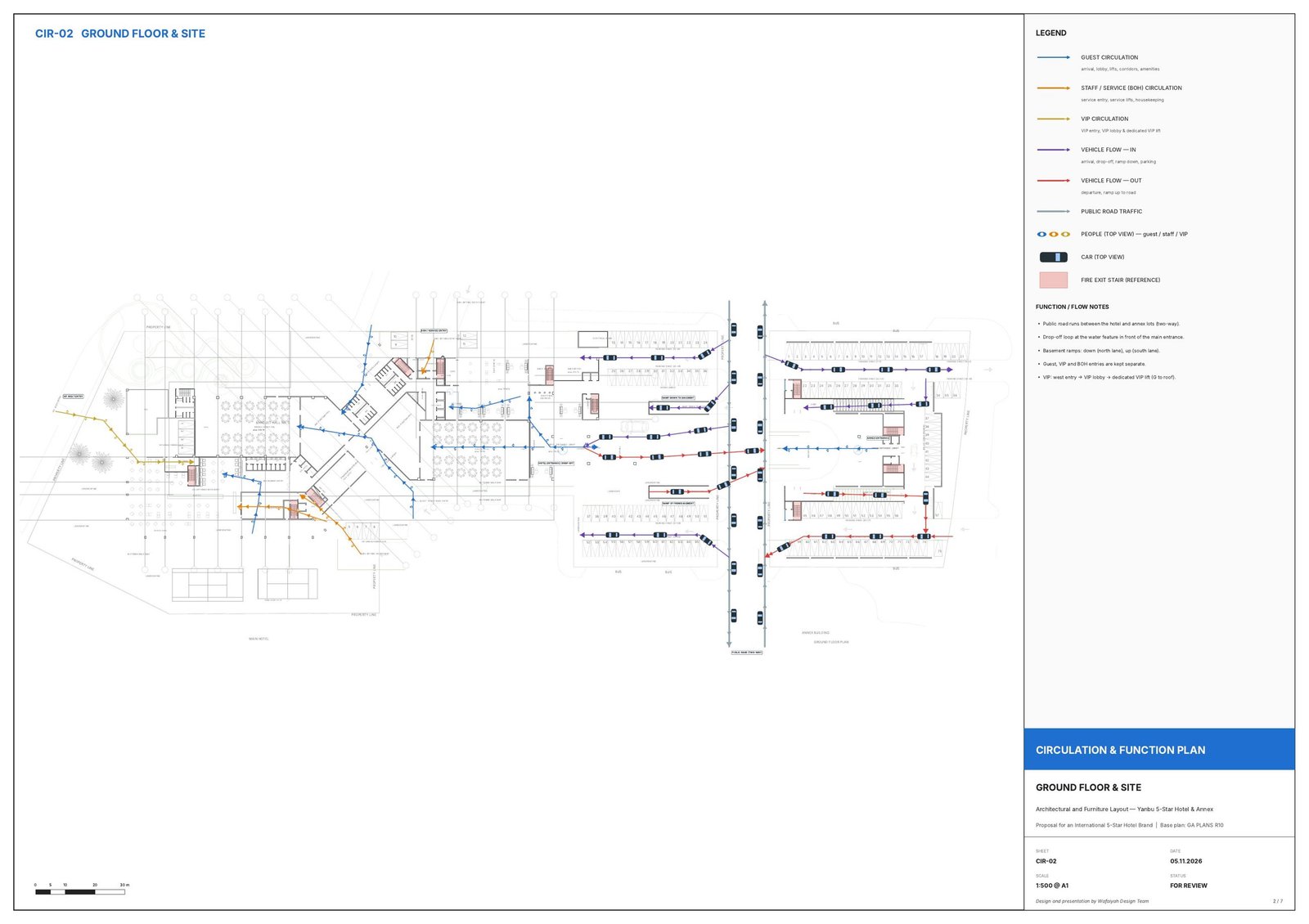
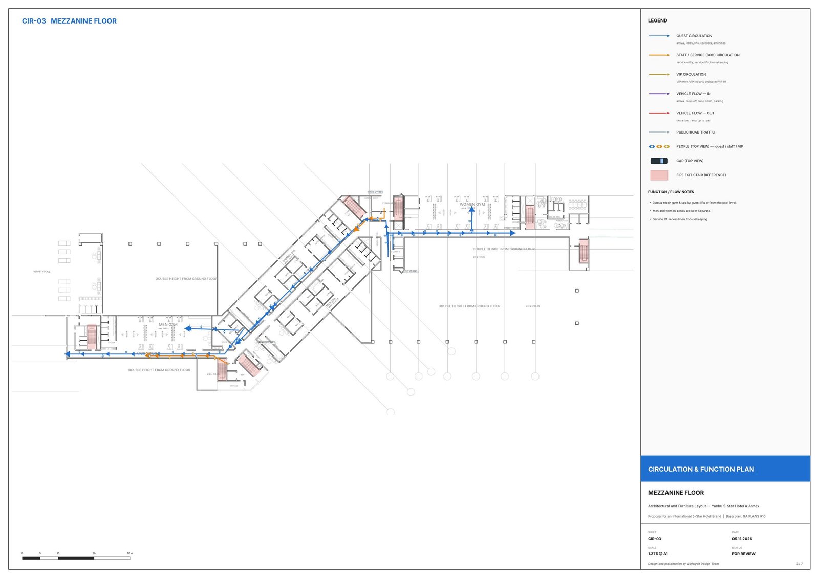
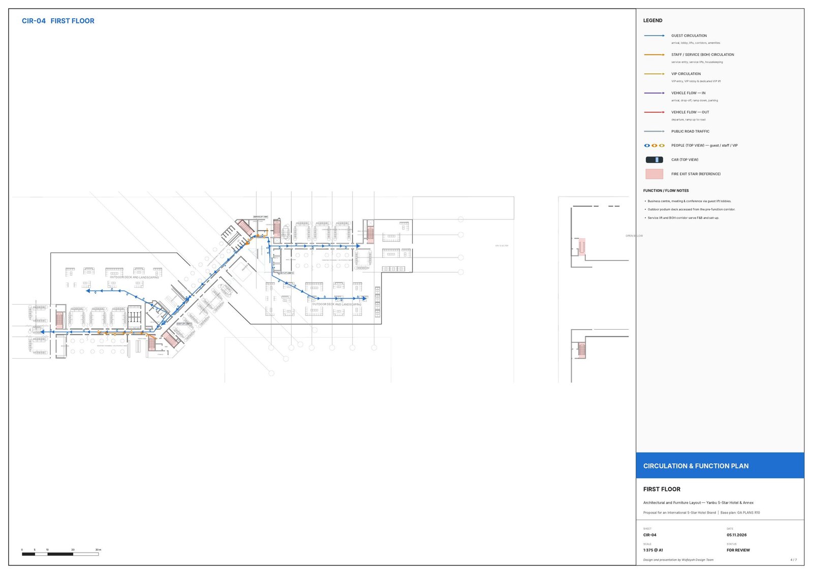
Separate entries for guests, banquet guests, VIPs and service; two guest lift lobbies and separate service lifts.
- Guests: porte-cochère → lobby → reception → lifts A or B → rooms and amenities.
- Banquet guests: own pedestrian entry → pre-function → halls, without crossing the hotel lobby.
- VIP: west entry and garage → VIP lobby → dedicated VIP lift.
- Service: north service entry and loading → back-of-house corridor → service lifts → housekeeping on every floor.
- Vehicles: drop-off loop at the fountain; basement ramp down (north lane) and up (south lane).
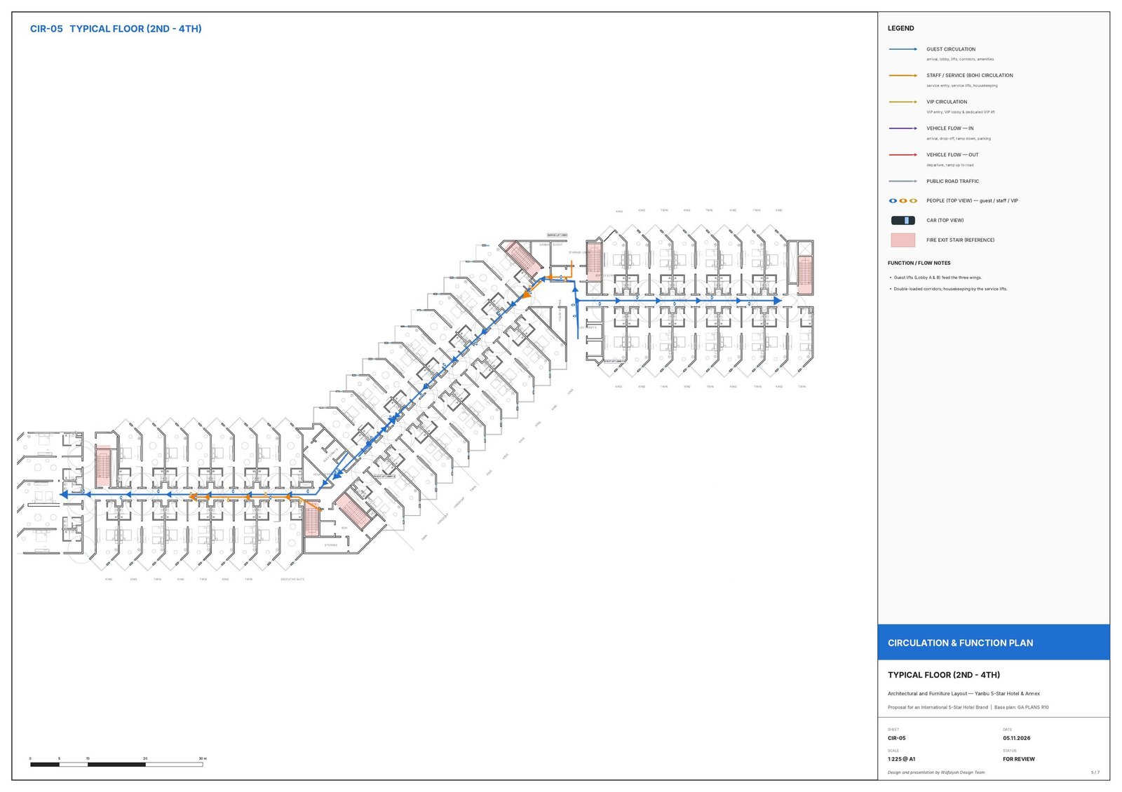
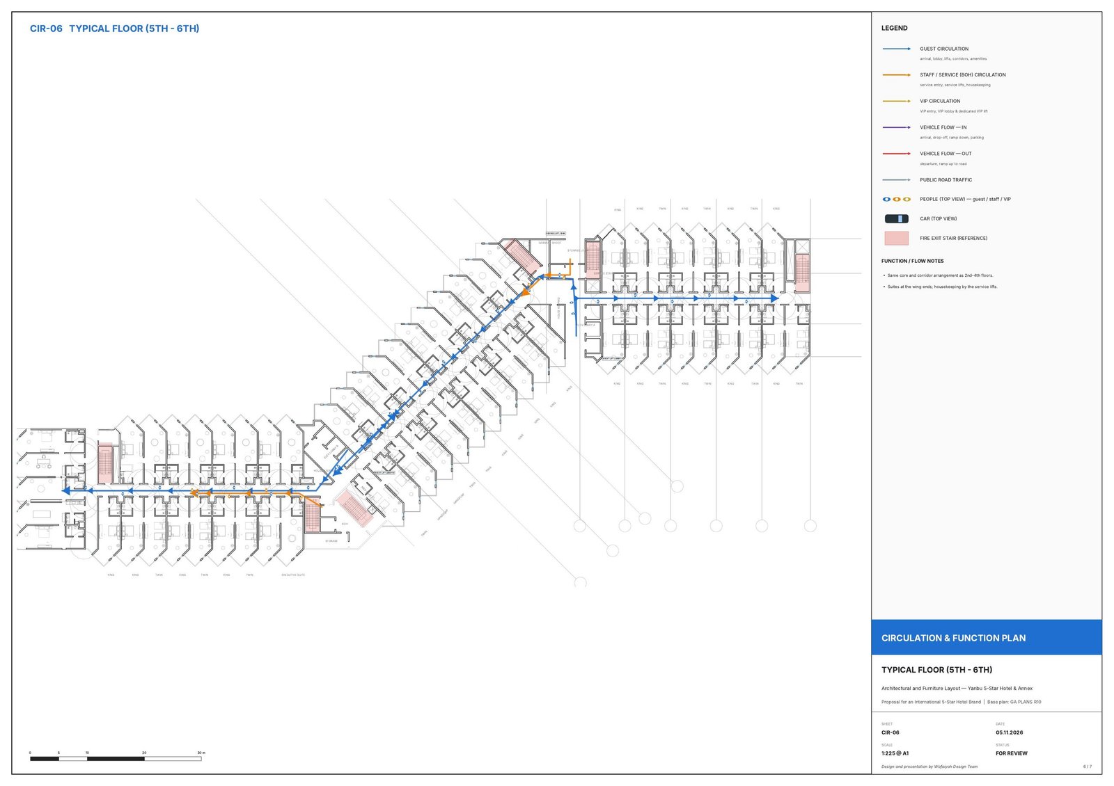
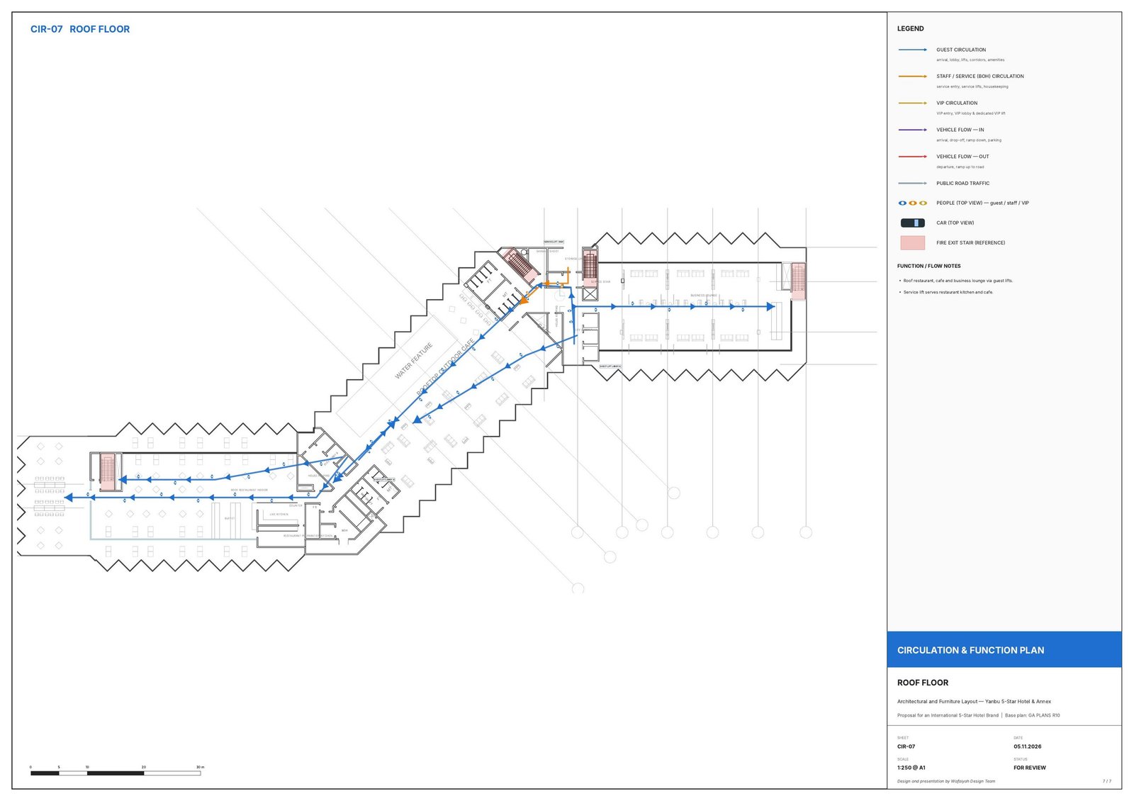
Space relationships – bubble diagrams
Proof of planning: which spaces connect directly, and where service stays apart from guests.
Vertical diagram – how the floors stack and connect
Horizontal diagram – ground floor adjacencies
Areas from the verified R17 space program.
Lifts – traffic analysis
CIBSE Guide D round-trip-time method with hotel criteria (interval 30–50 s, 5-star ≤ 40 s; 10–15 % of population in 5 minutes).
| Guest lifts | 6 (2 groups × 3 – Lobby A and Lobby B) |
| Car | 1,275 kg · 17 persons · 2.0 m/s |
| Floors served | B, G, M, 1F, 2F–6F, Roof |
| Round trip time | 117.8 s |
| Interval per group | 39.3 s ✓ (5-star ≤ 40 s) |
| Handling capacity (5 min) | 37 % of population ✓ (≥ 12 %) |
| With only 2 lifts per group | 58.9 s ✗ – so 3 per lobby are kept |
| Keys per guest lift | 38 |
| Service lifts | 3 ✓ (minimum 2 for 228 keys) |
| Fire-fighting lift | 1 per fire-fighting shaft (SBC 801) – service car, protected lobby |
Car size to be confirmed by the lift supplier; one stretcher car (1.1 × 2.1 m) per core.
Water storage & drainage
Tanks below the basement slab, shown as hidden lines on the basement plans.
| Potable water demand (design day) | 229.5 m³/day (≈ 1,007 L per key) |
| Domestic water tank – 2 days | 480 m³ · 2 compartments 8.0 × 10.0 m × 3.0 m |
| Fire water tank | 126 m³ · 7.0 × 6.0 m × 3.0 m (NFPA 13 / 14) |
| Irrigation tank (TSE) | 30 m³ · 4.0 × 2.5 m × 3.0 m |
| Total water storage | 636 m³ – below the basement slab |
| Sewage flow | 191 m³/day (85 % return) |
| Septic / holding tank | 234 m³ · 2 tanks 6.0 × 6.5 m × 3.0 m – back-up to the RCJY sewer network |
2-day storage to be confirmed with RCJY Utilities; fire reserve by the fire consultant. Irrigation uses TSE.